Heizungssteuerung
Demand-led control for 8 heating circuits · KiCad hardware project
Currently in development · in-house reference project
- ESP32-S3
- 8 thermal actuators
- 9× PT1000
- 0–10 V pump output
- 230 V digital inputs
- CAN bus
- 4-layer PCB
- 156 × 87 mm
- 43 test points
- LTspice
An ESP32-S3-based single-room and heating-circuit controller for a manifold with eight heating circuits: eight thermal actuators, nine PT1000 sensors and a 0–10 V output that runs the feed pump only as hard as the actual heat demand requires.
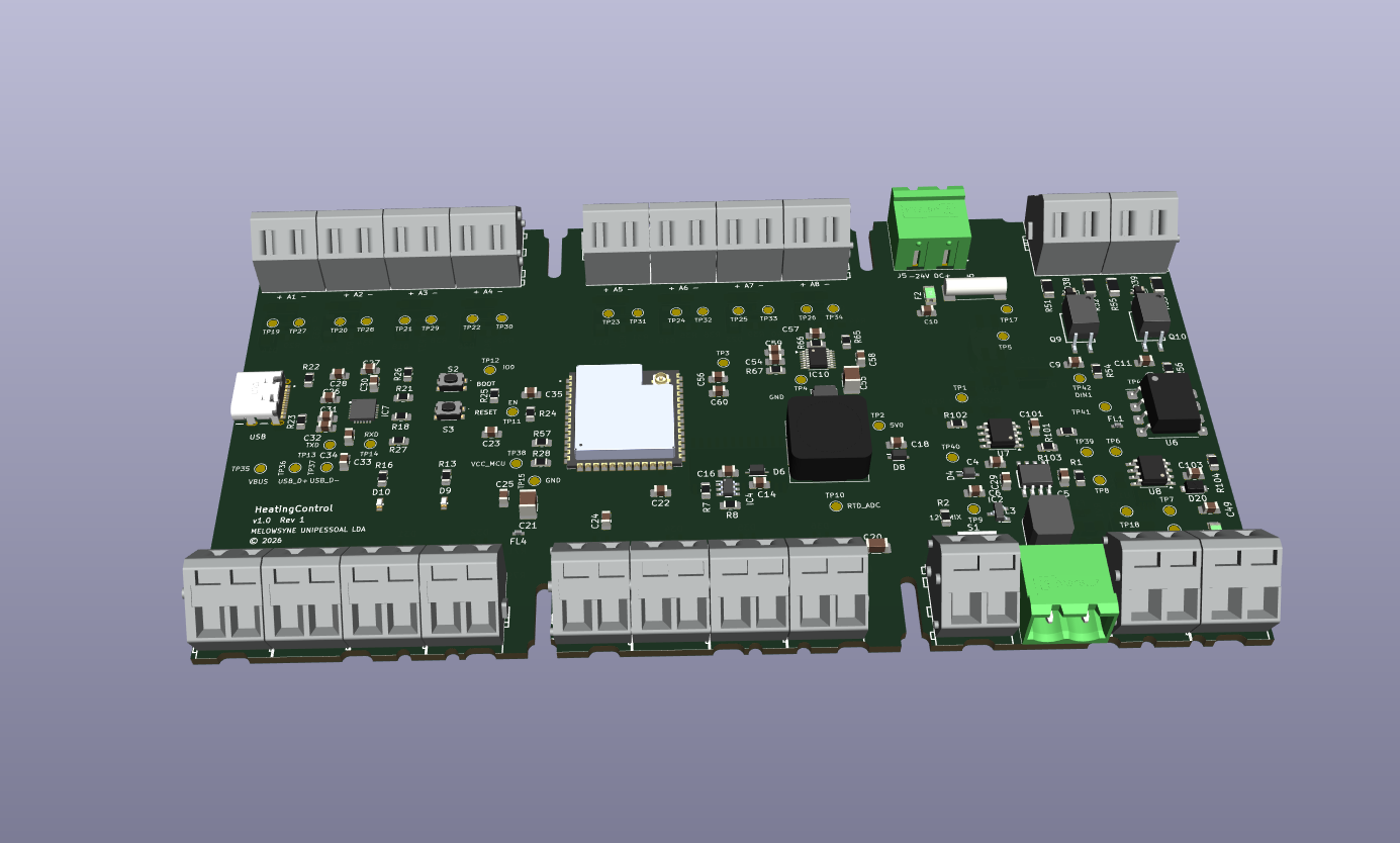
The Heizungssteuerung (HeatingControl / ActuatorBoard) is a KiCad hardware project for an ESP32-S3-based single-room and heating-circuit controller for a heating manifold with eight circuits. The board is a self-contained, demand-led controller for eight heating surfaces: it opens and closes the manifold valves through thermal actuators, detects the saturation of each circuit at its return line and drives the high-efficiency feed pump only as hard as the actual heat demand requires.
System concept
The heat generator feeds a hydraulic separator at the head of the manifold through its own pump, which hydraulically decouples the generator and consumer circuits. The high-efficiency feed pump draws heat from the separator and supplies the eight heating surfaces.
The measuring points and actuators are:
- eight thermal actuators (24 V), each opening and closing the valve of one heating circuit at the manifold;
- eight PT1000 sensors in the return line of each circuit, detecting the saturation of the heating surface — the return temperature rises once the surface is warmed through;
- one PT1000 on the supplying circuit, measuring the temperature of the circuit that feeds the manifold;
- one 0–10 V output providing the setpoint for the high-efficiency feed pump.
Control principle: from the return temperature of each circuit the firmware derives how far the associated heating surface is already warmed through. This yields the heat demand, which determines both the valve positions and, via the 0–10 V output, the delivery rate of the feed pump. The pump therefore runs only as hard as necessary, which lowers auxiliary energy consumption and the return temperature to the generator.
Functional scope
- Controller: ESP32-S3-WROOM-1U-N16R8 with Wi-Fi/BLE, 16 MB flash and 8 MB PSRAM.
- USB: USB-C with a CP2102N USB-UART bridge plus BOOT and RESET buttons.
- CAN: TJA1051 transceiver with NUP2105 ESD protection on a Phoenix connector.
- Temperature: nine PT1000 sensors through a 16-channel 74HC4067 multiplexer onto one ADC channel of the ESP32.
- Actuators: eight 24 V outputs, low-side switched by PMV37ENEAR MOSFETs with freewheeling and TVS diodes.
- 230 V digital inputs: two mains-rated inputs, galvanically isolated through SFH628A optocouplers.
- 0–10 V output: galvanically isolated through an IL300 linear optocoupler and MCP6H01 op-amps.
- Power supply: 24 V input with a separately fused actuator branch (4 A slow-blow) and logic branch (200 mA) with common-mode choke, 5 V (LT1934) and 3.3 V (LT8610) rails, plus a separate 12 V island (LT3010 LDO) for the 0–10 V stage.
Board key data: four layers, 156.3 × 86.5 mm, 270 footprints including 43 test points, 168 nets, developed in KiCad 10.
PT1000 measuring chain
Each sensor hangs on a precision reference divider of 2.2 kΩ (0.1 %, 25 ppm) against 3.3 V, with the PT1000 forming the lower branch. A 4.7 kΩ series resistor and an RC low-pass follow; a BAV99 dual diode clamps the input to GND and 3.3 V and protects the multiplexer against line disturbances. All nine channels run through the 74HC4067, whose filtered output feeds the ESP32 ADC. The excitation current is around 1 mA, so self-heating of the sensor remains negligible. The front-end is verified in LTspice, including filter behaviour, fault cases and interference coupling.
Actuators — current path and fusing
The 24 V for the actuators runs from the supply input through the actuator fuse to the terminals; the return current flows from the MOSFET sources directly back to the input over a separate power ground and touches neither the logic choke nor the logic ground. The regulators hang on their own branch, so a separate 24 V circuit for the actuators is not required.
The current budget is based on typical 24 V thermal actuators with a PTC heating element (1–2 W): 40–85 mA per actuator in continuous operation, but 250–300 mA during the start-up phase of up to two minutes — 2.0 to 2.4 A with all eight starting at once. The actuator fuse was therefore changed from a fast 1 A type to a 4 A slow-blow type (Schurter UMT 250), and the power supply is specified at 24 V / 3 A or more; optionally the firmware can stagger the start-up.
0–10 V output
A PWM signal from the ESP32 is smoothed by two RC stages. A servo amplifier drives the LED of the linear optocoupler and linearises the LED current through the feedback of the first photodiode. On the isolated side, a transimpedance amplifier converts the current of the second photodiode into the output voltage, giving 10 V at a 3.3 V input while the isolation between the two grounds is fully preserved. The optocoupler was switched from a DIP-8 to an SMD-8 gull-wing package with a custom footprint and 3D model.
Connections and test points
The terminals are numbered in installation order: actuators along the top edge, the associated sensors directly opposite along the bottom edge, so that actuator and sensor of one heating circuit always face each other. The 230 V inputs, the 24 V supply and the CAN bus sit at the top right, the supply of the isolated 0–10 V island and the 0–10 V output at the bottom right, USB-C on the left. All terminals are labelled on the silkscreen with function and polarity.
43 SMD test points on the top side cover all supply rails, both ground potentials, the multiplexer output, the 0–10 V output, CAN before and after the transceiver, USB, the boot and reset signals, and the gate and output of every actuator channel. Each heating circuit can therefore be measured separately before and after its MOSFET.
Simulation and verification
The core circuits are verified in LTspice: the 5 V and 3.3 V buck converters and the 12 V LDO, the actuator output stage with switching edges and freewheeling, the 0–10 V output via the IL300 (linearity and isolation), the 230 V optocoupler input and the complete PT1000 measuring chain with filter, fault and interference cases. ERC, DRC and netlist checks run in a KiCad Docker container, and scripted changes to schematic and PCB are verified by comparing the reports before and after each change.
Project status
The schematic is complete and the components are placed; the PCB is deliberately not yet routed. Open items are the final placement according to the layout recommendations of the regulators and the analog measuring chain, routing with ground zones while respecting the isolation zones, adapting the placement to the intended Phoenix Contact enclosure, and the actuator mapping in the firmware.
Project competencies
- control concept for demand-led heating-circuit regulation
- precision temperature measurement with PT1000 sensors
- switching of inductive 24 V actuator loads
- galvanically isolated 230 V inputs and 0–10 V output
- fusing and current-budget design
- ESP32-S3 hardware development with CAN and USB
- multilayer PCB design in KiCad
- LTspice circuit simulation
- custom footprints and generated 3D models
- test-point concept and scripted verification