Brunnensteuerung
From modular prototype to production-ready pump controller
In final phase · in-house reference project
- ESP32-S3
- DIN-rail prototype
- FreeCAD · 3D printing
- OTA firmware
- ESP-IDF · FreeRTOS
- Secure updates (TLS · RSA)
- 24 V SELV PCB
- 6-layer · KiCad
- LTspice · ngspice
- SMD assembly by reflow oven
The full journey of a networked well- and pump-control system — from a flexible DIN-rail prototype through a modular OTA firmware platform to a compact, self-manufactured 24 V control PCB.
The basic idea is to control a well pump through an external solid-state relay (SSR). Because the SSR sits off the board, the pump power can be chosen almost freely, and only 24 V extra-low voltage is present on the board itself. The original test setup used off-the-shelf modules: an ADS1115 module as the A/D converter, a 5 V DIN-rail power supply and an ESP32 module. A temperature and humidity sensor was also fitted to monitor temperature and humidity inside the electrical enclosure.
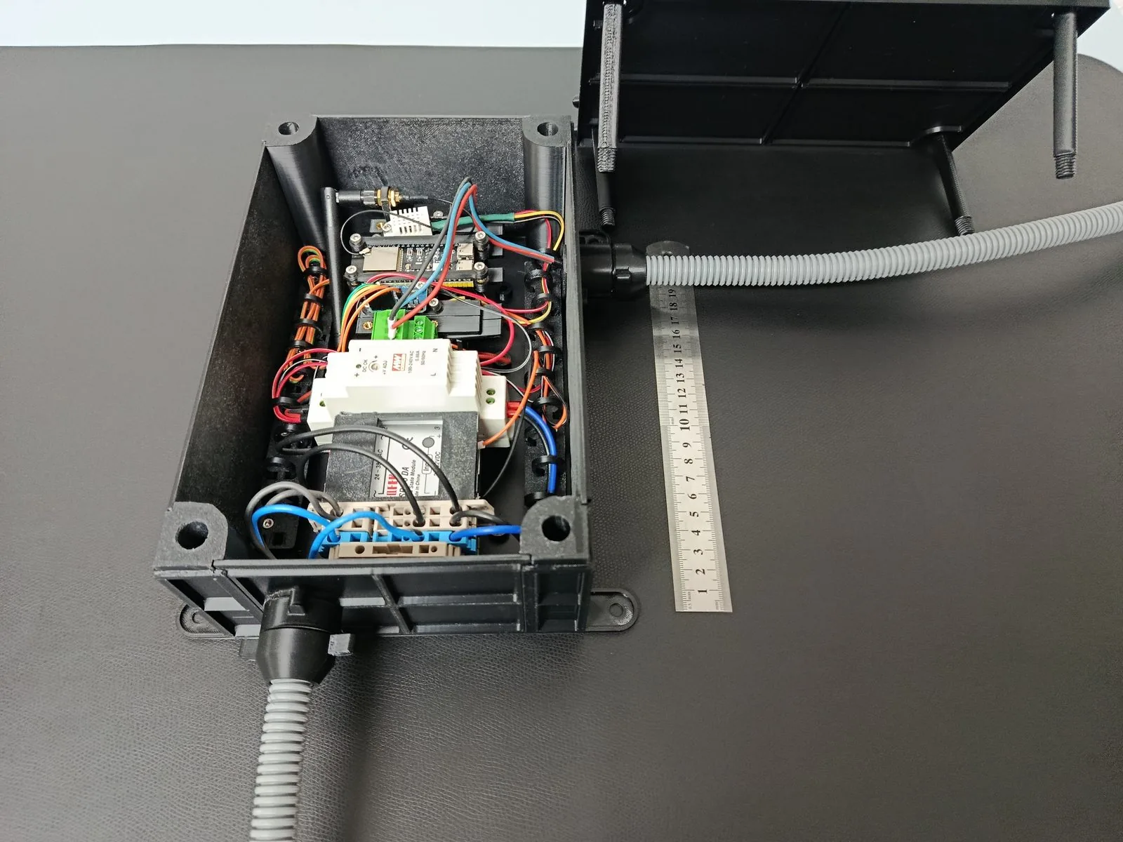
The modular setup was useful for running preliminary tests with the 1 kW deep-well pump and for implementing a basic controller in C on the ESP32-S3. Flashing over Wi-Fi via OTA update was already in use at this stage, despite a weak signal of -90 dBm.
Based on the requirements gained from this, the modular prototype evolved into a dedicated circuit and PCB, developed with KiCad.
Component selection and manufacturability
From the outset, components were selected with later series production in mind. All components are RoHS-compliant. The Moisture Sensitivity Level (MSL) was also taken into account: it specifies whether a component has to be stored particularly dry or dried (“baked”) before soldering after a longer storage period.
If components are processed by wave or selective soldering in series production, their resistance to soldering heat (RSH) can additionally be used as a selection criterion.
The controller is designed for use in covered outdoor areas. An operating temperature range of at least 0 to 55 °C is required; throughout, components specified for –20 to 85 °C were used, which provides a substantial margin.
Another criterion was the long-term availability of the components. This avoids components being discontinued during the product’s lifetime and replacement parts having to be re-qualified.
For sale in the EU, a conformity assessment for the CE mark is required, including EMC testing. For the US market, FCC approval applies accordingly. The design is prepared for this; the tests take place before series production.
Protective circuits and testability
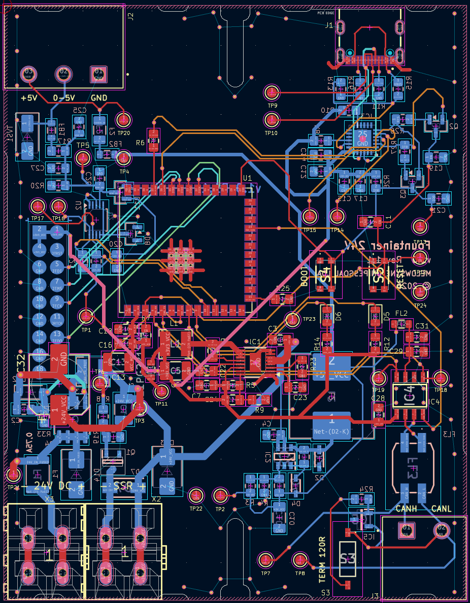
Overvoltage protection and various protective circuits were important in the circuit design, so that the board stays protected in most fault cases and safe operation is ensured. The 24 V input has a self-resetting fuse, reverse-polarity protection and transient-voltage-suppression (TVS) diodes. The sensor input tolerates fault voltages up to ±24 V, and the CAN bus is ESD-protected. In addition, 24 test points and a JTAG pad field were added so that the board can later be tested and programmed automatically with spring-loaded probes during production.
After thorough verification of the circuit with LTspice, ngspice and the KiCad tools (ERC/DRC), a final visual check followed: texts, positions of the component labels, trace widths and the minimum clearances between traces.
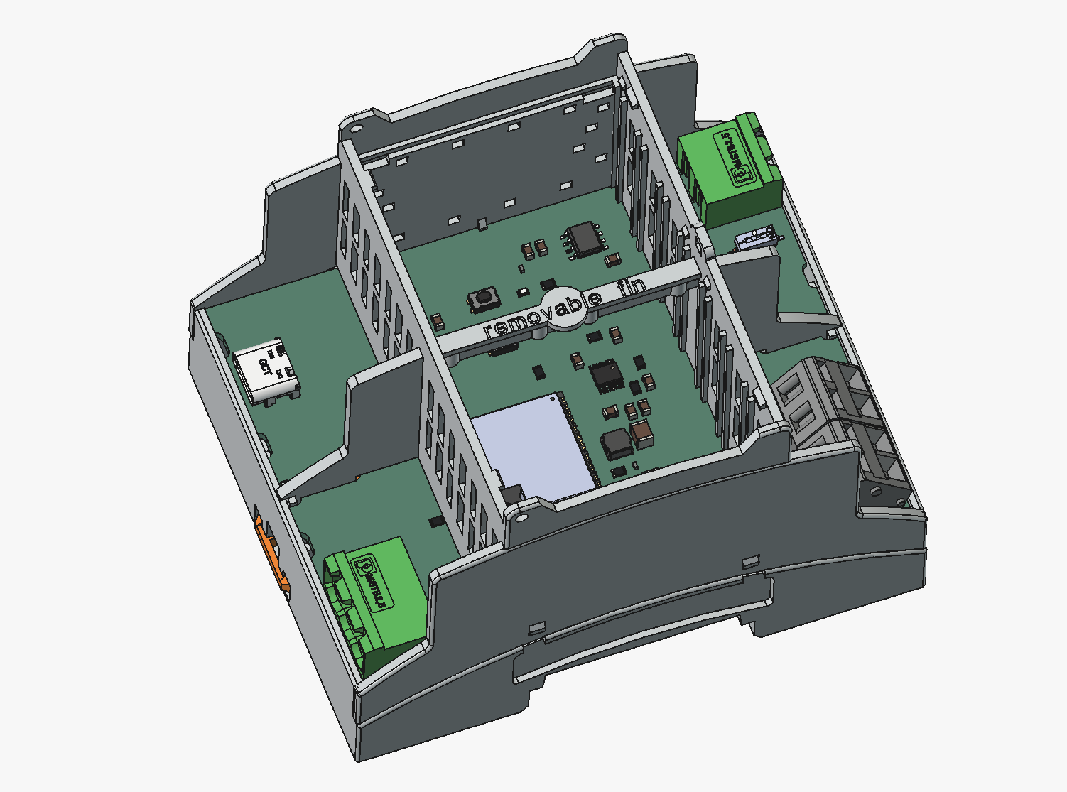
For the enclosure I chose a Phoenix Contact DIN-rail housing (BC 71.6), as it fits the DIN rail well, is readily available and offers many customisation options. Particularly for companies aiming at series production, it is a good choice for devices with a single board.
To make sure the board actually fits into the enclosure, the PCB design had to be loaded into the 3D model of the housing. This makes it possible to check that all components have room and that the connectors line up with the openings in the enclosure.
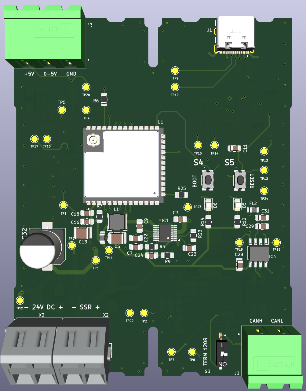
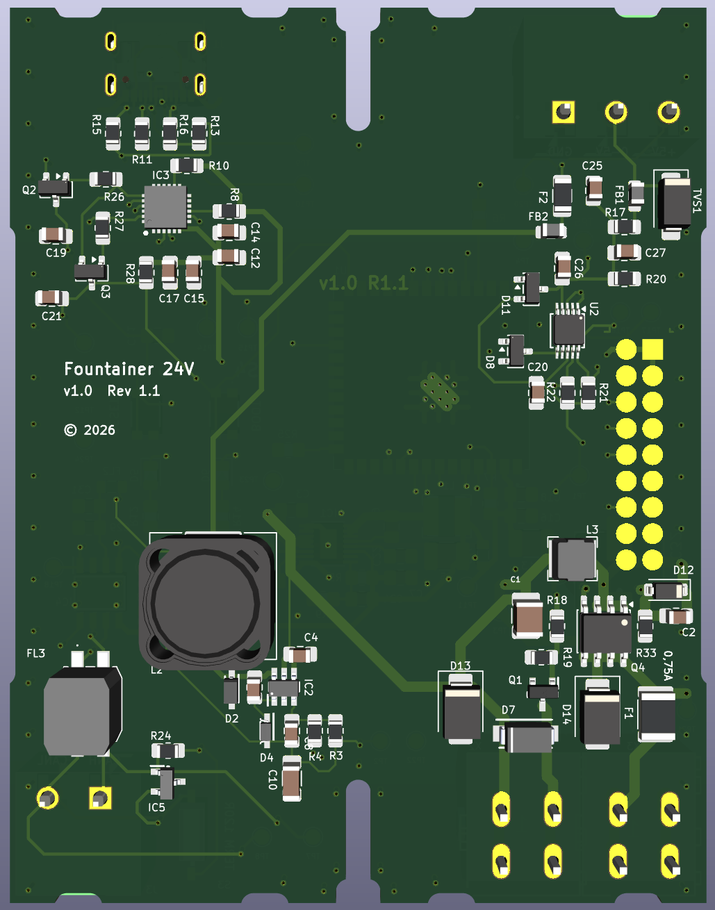
After the final checks (circuit, component positions, ERC/DRC, clearances and traces) the board was released for manufacturing. I prefer to do the assembly myself. It saves time, is cheaper, and problems in sourcing components are easier to handle. Due to sanctions, for example, some components were unavailable and had to be ordered from local distributors.
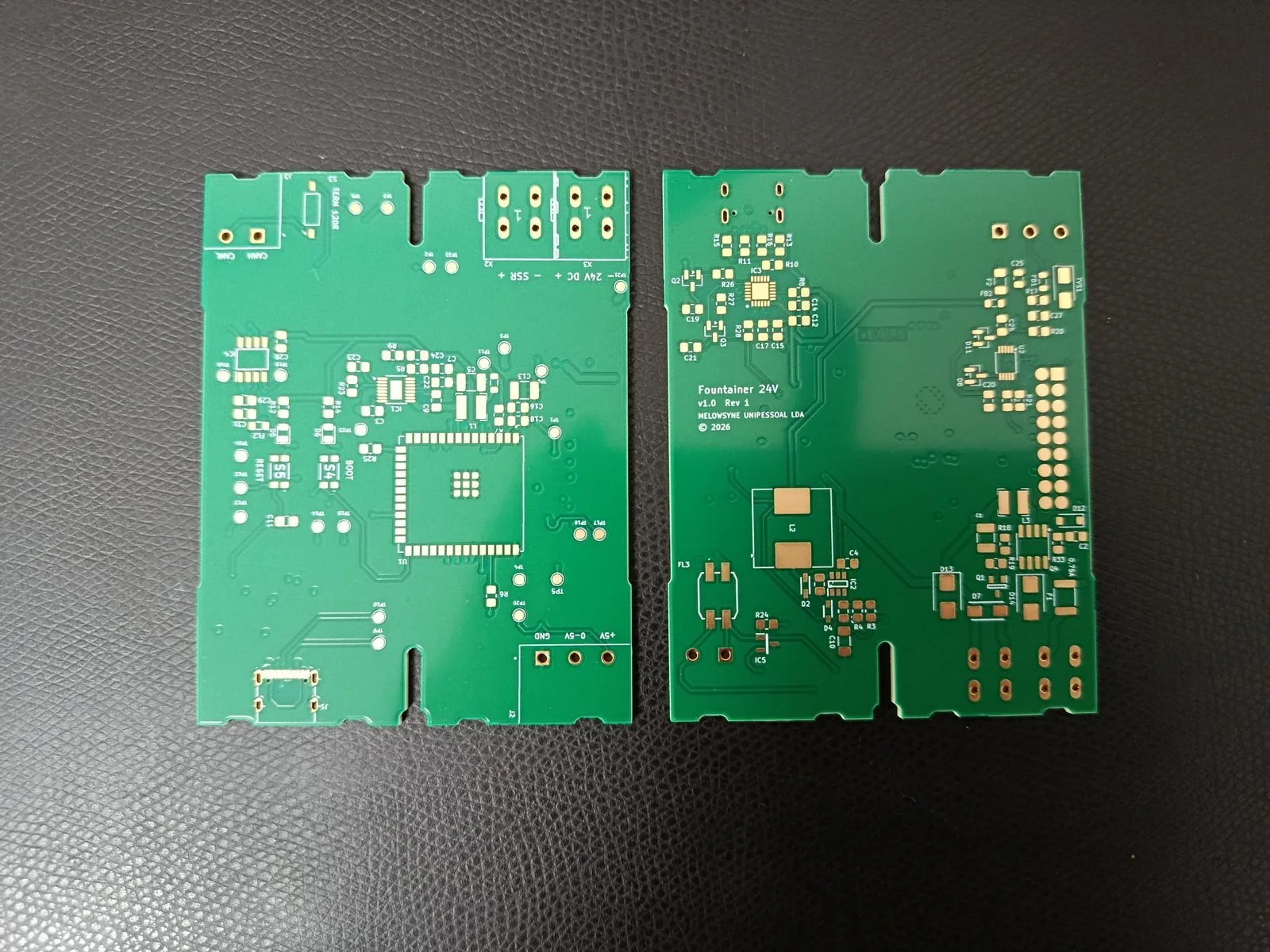
The board was ordered together with a solder-paste stencil to apply the paste to the pads on the front and back. A self-printed alignment jig was used for this, freely available on the internet and made specifically for the stencils of the board manufacturer used.
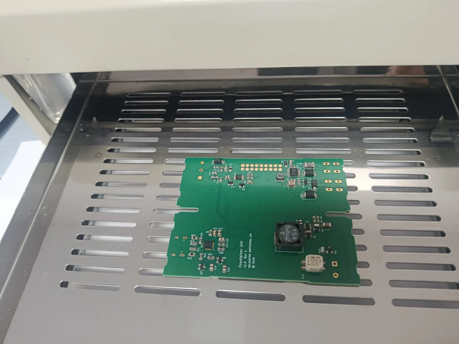
The back side was assembled first, as the lighter components are located there. During the second pass this side faces down and is then held only by the surface tension of the solder. The front side was then populated and likewise reflow-soldered.
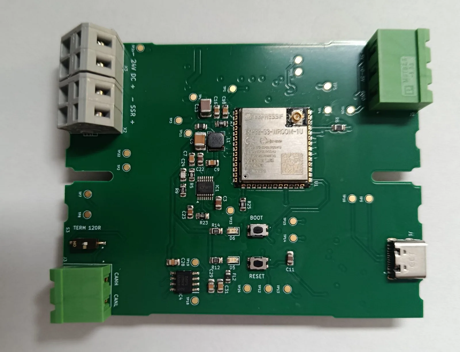
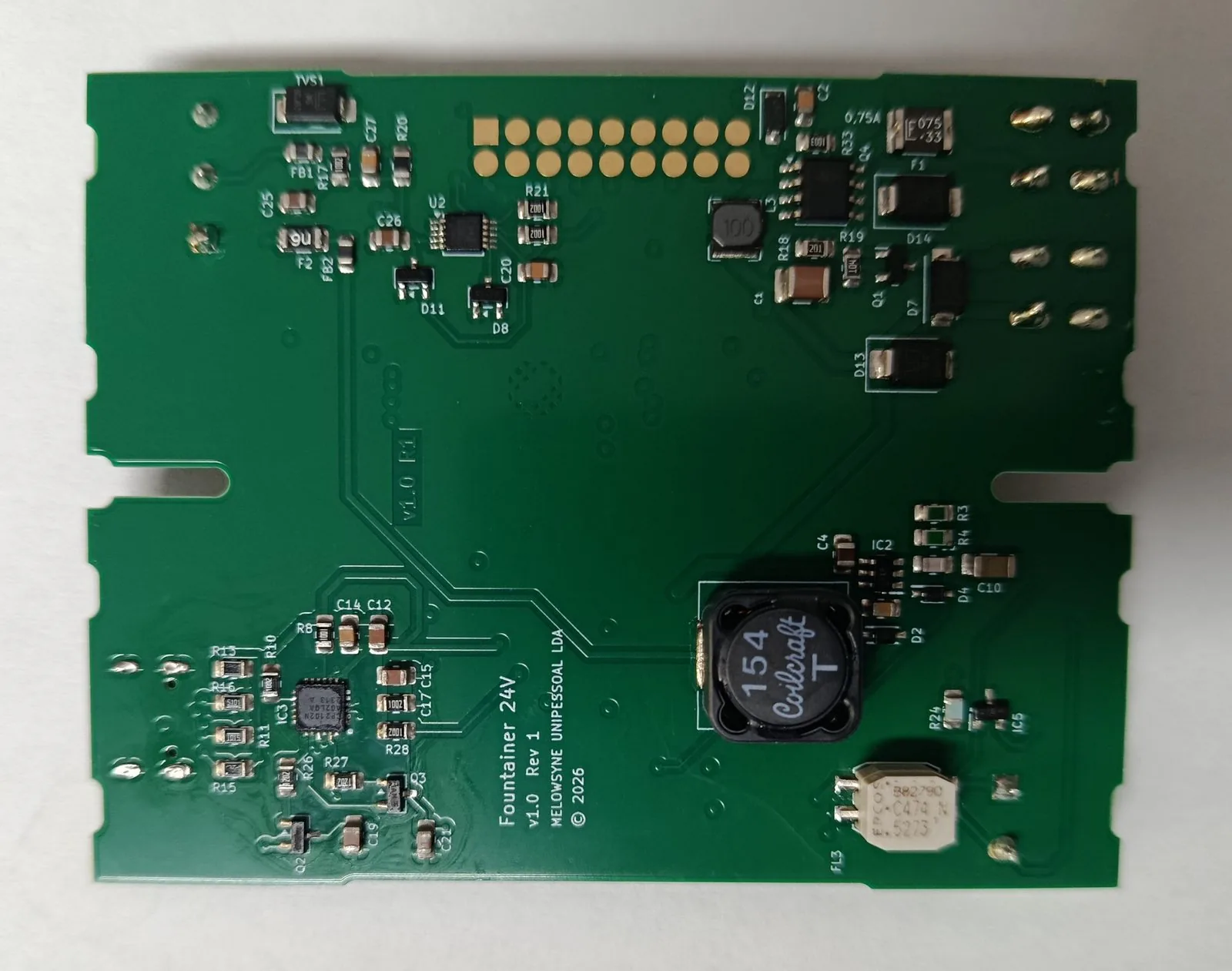
Both sides are now populated and soldered. The SMD components were soldered with a low-temperature solder paste Sn42/Bi57.6/Ag0.4 (melting point 138 °C, reflow peak approx. 160 °C). This is sufficient here, as the components stay at a moderate 40 to 50 °C in operation. The Wago spring-clamp terminals and the Phoenix Contact connectors were hand-soldered with regular solder (melting point approx. 220 °C).
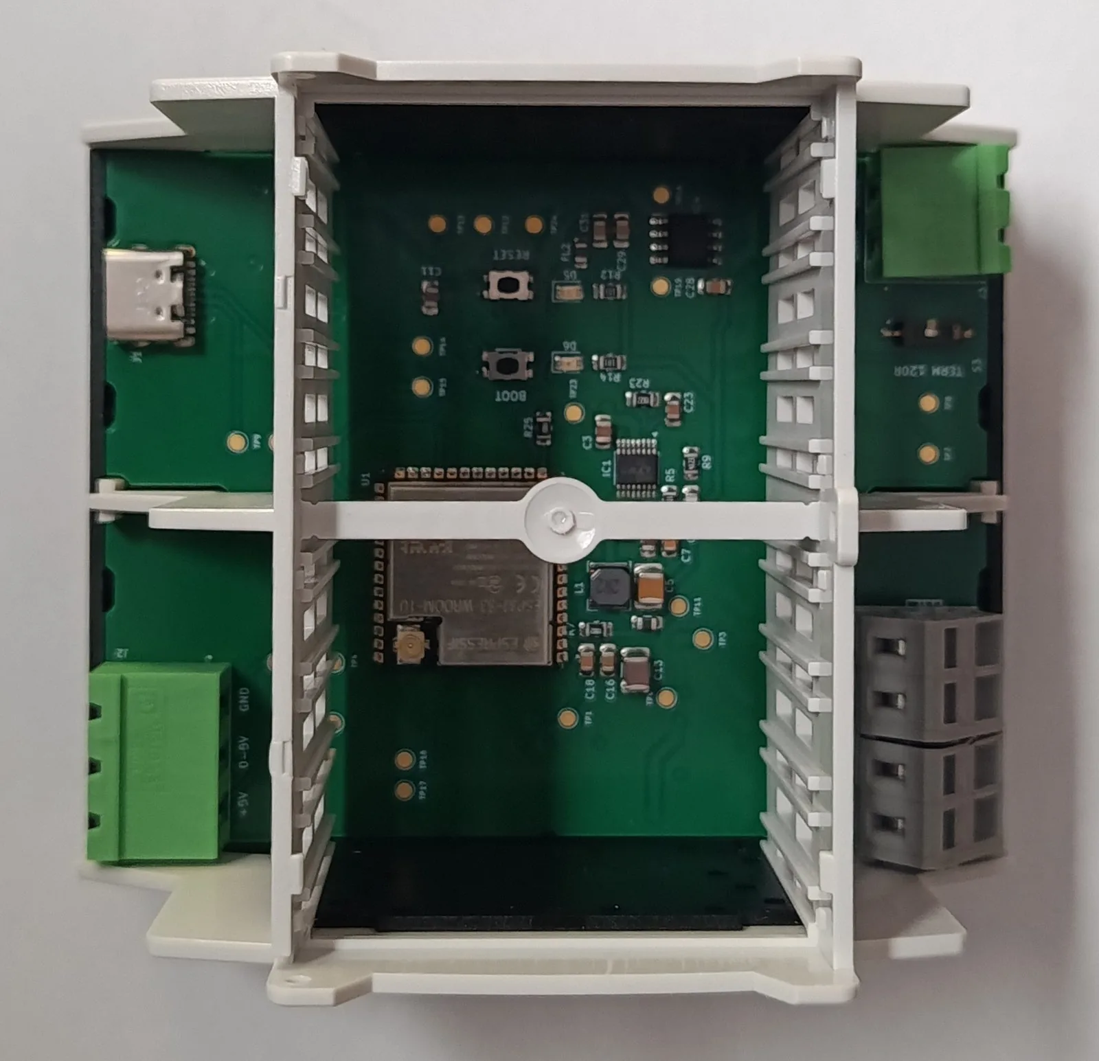
The board fits into the enclosure as planned, and the components do not touch the enclosure walls. A housing insert can be fitted into the upper cut-out to bring out buttons and LEDs and to mount the antenna.
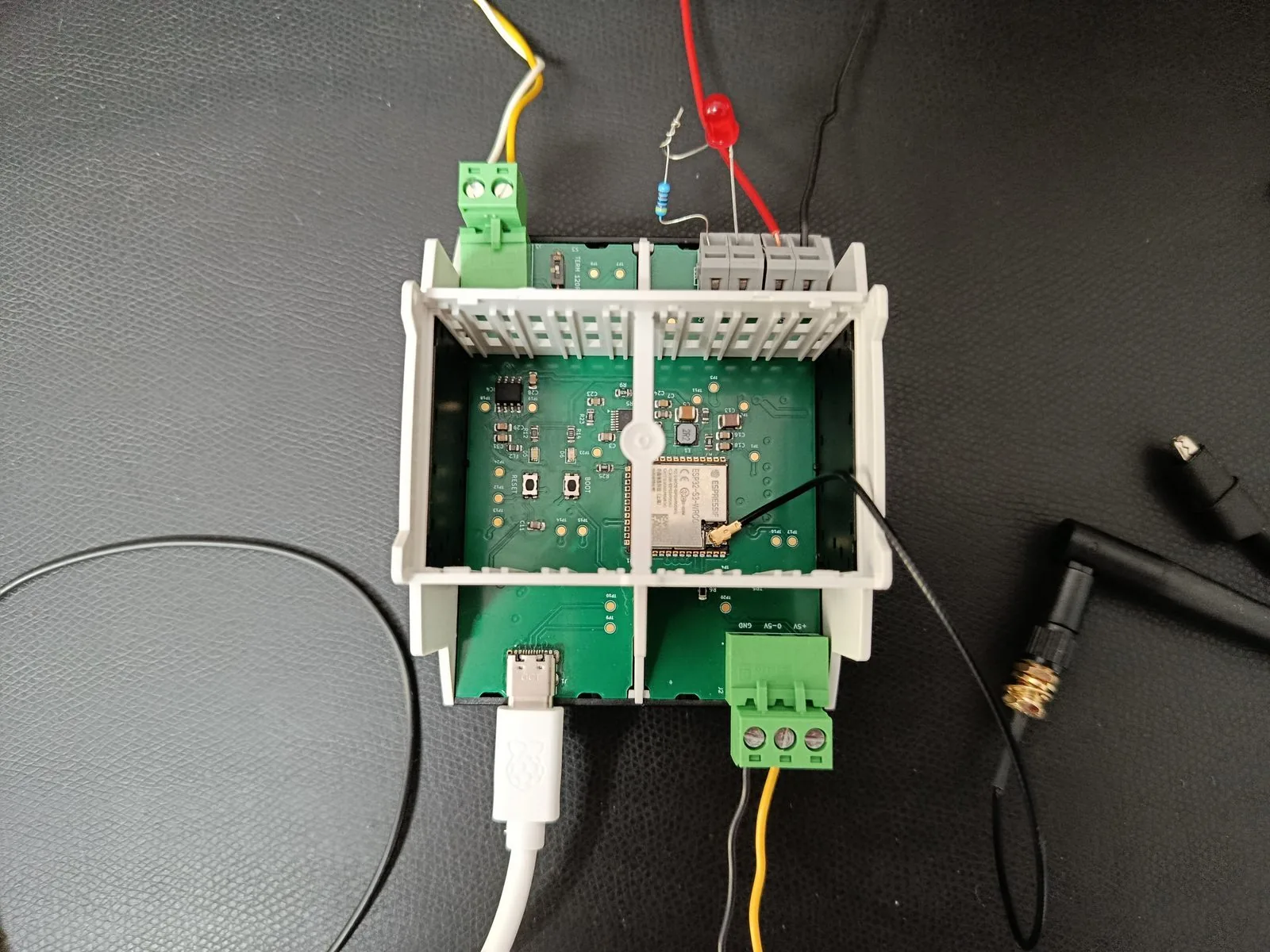
First functional test of the individual inputs and outputs:
- Switching of the SSR output is tested with a simple red LED in series with a 4.7 kΩ resistor.
- Power is supplied at 24 V from a bench power supply.
- The CAN bus is tested over a separate CAN cable. At the other end a Raspberry Pi with an MCP2515 shield is connected. Both bus ends are terminated with 120 Ω. The CANopen protocol at 250 kbit/s is currently implemented.
- The 0–5 V input for the pressure sensor is simulated with the bench power supply. The supply is stepped through values between 0 and 5 V and the resulting calculated pressure is compared with the expected value.
- The Wi-Fi antenna for the ESP32-S3 is mounted directly on the module (u.FL socket) and tested over the lab Wi-Fi.
- The inputs and outputs are measured with the oscilloscope and the signal waveforms are documented.
Result of the test run
All tests were successful except for the 24 V power supply. It turned out that plugging in the 24 V cable while live (hot-plug) produces a voltage spike that had not been considered in the design. It only affects the 5 V converter and the IC for CAN communication. An electrolytic capacitor (47 µF/63 V) must be retrofitted at the 24 V input to damp the spike. It is already included in the design shown in Figure 4.
Firmware
The firmware is designed for unattended continuous operation on a well pump. Every layer that can fail is monitored and repairs itself: Wi-Fi, the encrypted connection, the sensors and the pump control loop.
Architecture
Access to the hardware, such as switching the SSR relay or reading the pressure sensor, takes place exclusively through data points. Hardware access and control logic are thus strictly separated. A command from the network never reaches the pump directly, but always passes through the control logic, which checks every request for admissibility. Control and network data are handled uniformly and protected by access rights. New data points are defined in one central place. This allows the platform to be transferred to other control tasks with little effort.
Protecting the pump and the well
The pump control is pressure-driven and works entirely locally, i.e. also without a network or server connection. Several protective functions act independently of any remote control:
- Dry-run protection: if the pressure does not rise sufficiently after switch-on, the pump is shut off.
- Minimum run and minimum rest times as well as a limit on the number of starts per hour prevent harmful cycling.
- Maximum run time as protection against leaks or open lines.
- Sensor monitoring: a faulty pressure sensor is detected and the pump enters a safe state.
Faults remain stored until they are deliberately acknowledged. The controller also evaluates the pressure curve and thus distinguishes between normal draw-off, tank filling, suspected leak and pipe burst.
Self-healing and fault tolerance
A multi-level watchdog system monitors whether each function is actually working, not just whether it is running. In the event of a fault, the affected function is first restarted selectively, and only then the device. Before every restart the pump is safely switched off. A lock prevents endless restart loops. If the Wi-Fi fails, the controller keeps recording all measured values without gaps and transmits them as soon as the connection is back.
Remote configuration is also safeguarded. New network settings initially apply only on a trial basis. If no verified server connection is established with them, the device automatically reverts to the last working configuration. This also applies if the power fails during the changeover. A device can therefore never lock itself out permanently.
Secure communication
The connection is encrypted with mTLS. Device and server authenticate each other with certificates from a dedicated root CA. In addition, every message is authenticated with HMAC-SHA256, and replayed messages are detected and discarded.
Firmware updates (OTA)
Updates are loaded wirelessly into a second memory area while the running firmware remains unchanged. Every update is cryptographically signed. The device verifies the signature itself and only activates firmware from a trusted source. In the event of a faulty transfer or a manipulated image, the update is discarded and operation continues undisturbed. The switch to the new version is atomic: the controller is functional at all times, even if the power fails in the middle of an update.
Tested under real conditions
All functions were verified in stress tests on the real device, without a USB connection and exclusively via remote maintenance. The tests included a Wi-Fi outage, a power failure during the download, a power failure immediately after the update and an attempt to install a manipulated firmware image. All tests were passed. A weakness uncovered in the process was fixed and confirmed in a retest.
The source code, including architecture and test documentation, is publicly available: github.com/Melowsyne/fountainer_firmware
Are you planning a comparable project, from the hardware through the firmware to the server connection? Get in touch.